
More precise SEG-Y?
/The impending SEG-Y Revision 2 release allows the use of double-precision floating point numbers. This news might leave some people thinking: "What?".
Integers and floats
In most computing environments, there are various kinds of number. The main two are integers and floating point numbers. Let's take a quick look at integers, or ints, first.
Integers can only represent round numbers: 0, 1, 2, 3, etc. They can have two main flavours: signed and unsigned, and various bit-depths, e.g. 8-bit, 16-bit, and so on. An 8-bit unsigned integer can have values between 0 and 255; signed ints go from -128 to +127 using a mathematical operation called two's complement.
As you might guess, floating point numbers, or floats, are used to represent all the other numbers — you know, numbers like 4.1 and –7.2346312 × 10¹³ — we need lots of those.
Floats in binary
OK, so we need to know about floats. To understand what double-precision means, we need to know how floats are represented in computers. In other words, how on earth can a binary number like 01000010011011001010110100010101 represent a floating point number?
It's fairly easy to understand how integers are stored in binary: the 8-bit binary number 01001101 is the integer 77 in decimal, or 4D in hexadecimal; 11111111 is 255 (base 10) or FF (base 16) if we're dealing with unsigned ints, or -1 decimal if we're in the two's complement realm of signed ints.
Clearly we can only represent a certain number of values with, say, 16 bits. This would give us 65 536 integers... but that's not enough dynamic range represent tiny or gigantic floats, not if we want any precision at all. So we have a bit of a paradox: we'd like to represent a huge range of numbers (down around the mass of an electron, say, and up to Avogadro's number), but with reasonably high precision, at least a few significant figures. This is where floating point representations come in.
Scientific notation, sort of
If you're thinking about scientific notation, you're thinking on the right lines. We raise some base (say, 10) to some integer exponent, and multiply by another integer (called the mantissa, or significand). That way, we can write a huge range of numbers with plenty of precision, using only two integers. So:
$$ 3.14159 = 314159 \times 10^{-5} \ \ \mathrm{and} \ \ 6.02214 \times 10^{23} = 602214 \times 10^{18} $$
If I have two bytes at my disposal (so-called 'half precision'), I could have an 8-bit int for the integer part, called the significand, and another 8-bit int for the exponent. Then we could have floats from \(0\) up to \(255 \times 10^{255}\). The range is pretty good, but clearly I need a way to get negative significands — maybe I could use one bit for the sign, and leave 7 bits for the exponent. I also need a way to get negative exponents — I could assign a bias of –64 to the exponent, so that 127 becomes 63 and an exponent of 0 becomes –64. More bits would help, and there are other ways to apportion the bits, and we can use tricks like assuming that the significand starts with a 1, storing only the fractional part and thereby saving a bit. Every bit counts!
IBM vs IEEE floats
The IBM float and IEEE 754-2008 specifications are just different ways of splitting up the bits in a floating point representation. Single-precision (32-bit) IBM floats differ from single-precision IEEE floats in two ways: they use 7 bits and a base of 16 for the exponent. In contrast, IEEE floats — which are used by essentially all modern computers — use 8 bits and base 2 (usually) for the exponent. The IEEE standard also defines not-a-numbers (NaNs), and positive and negative infinities, among other conveniences for computing.
In double-precision, IBM floats get 56 bits for the fraction of the significand, allowing greater precision. There are still only 7 bits for the exponent, so there's no change in the dynamic range. 64-bit IEEE floats, however, use 11 bits for the exponent, leaving 52 bits for the fraction of the significand. This scheme results in 15–17 sigificant figures in decimal numbers.
The diagram below shows how four bytes (0x42, 0x6C, 0xAD, 0x15) are interpreted under the two schemes. The results are quite different. Notice the extra bit for the exponent in the IEEE representation, and the different bases and biases.
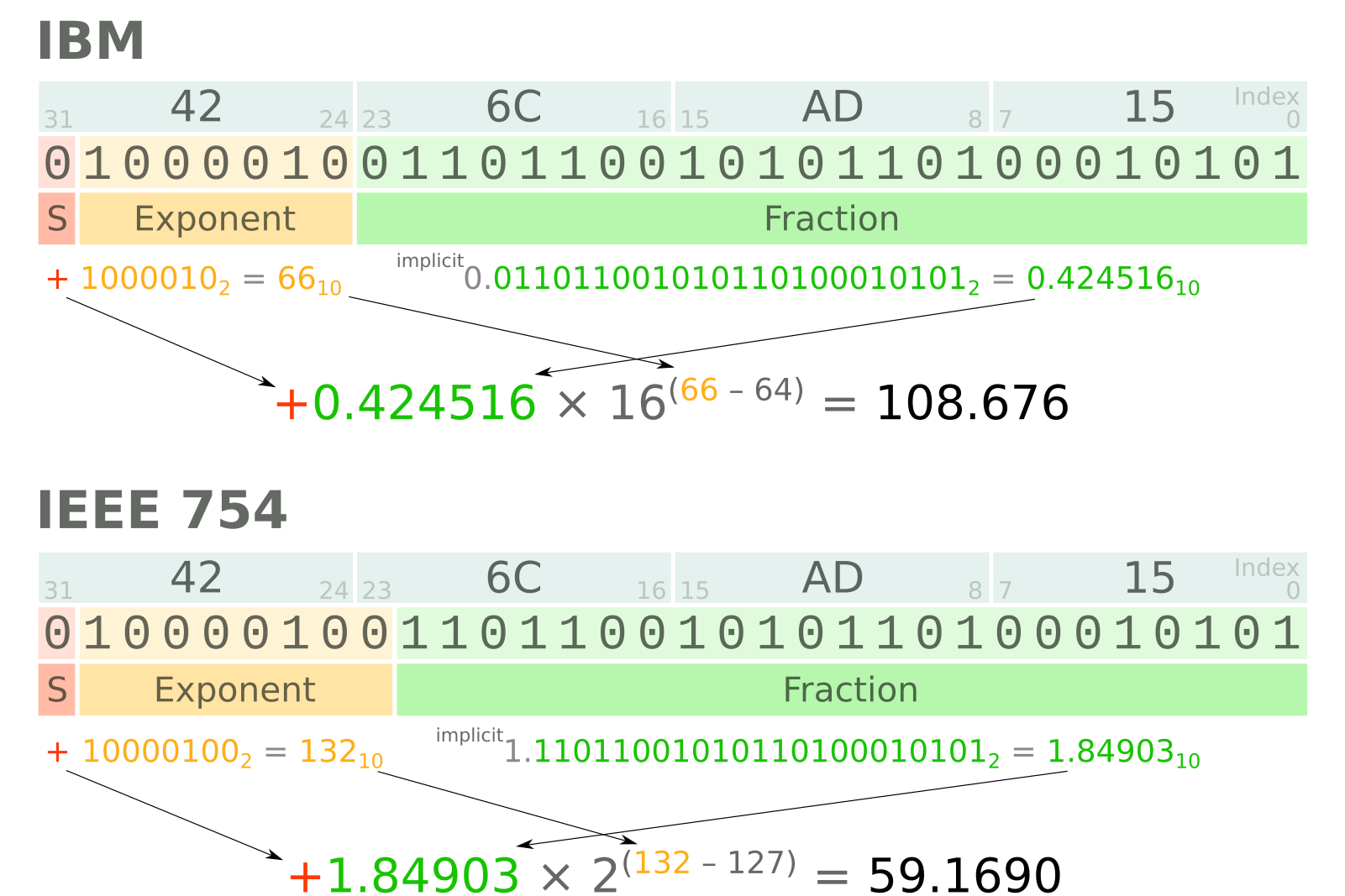
A four-byte word, 426CAD15 (in hexadecimal), interpreted as an IBM float (top) and an IEEE float (bottom). Most scientists would care about this difference!
IBM, IEEE, and seismic
When SEG-Y was defined in 1975, there were only IBM floats — IEEE floats were not defined until 1985. The SEG allowed the use of IEEE floating-point numbers in Revision 1 (2002), and they are still allowed in the impending Revision 2 specification. This is important because most computers these days use IEEE float representations, so if you want to read or write IBM floats, you're going to need to do some work.
The floating-point format in a particular SEG-Y file should be indicated by a flag in bytes 3225–3226. A value of 0x01 indicates IBM floats, while 0x05 indicates IEEE floats. Then again, you can't believe everything you read in headers. And, unfortunately, you can't tell an IBM float just by looking at it. Meisinger (2004) wrote a nice article in CSEG Recorder about the perils of loading IBM as IEEE and vice versa — illustrated below. You should read it.
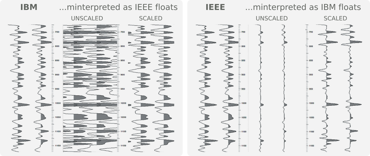
From Meisinger, D (2004). SEGY floating point confusion. CSEG Recorder 29(7). Available online.
I wrote this post by accident while writing about endianness, the main big change in the new SEG-Y revision. Stay tuned for that post! [Update: here it is!]


 Except where noted, this content is licensed